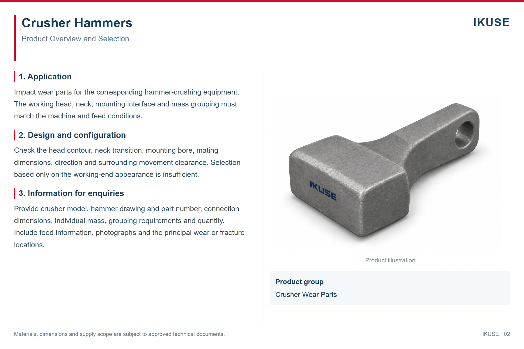
Product overview
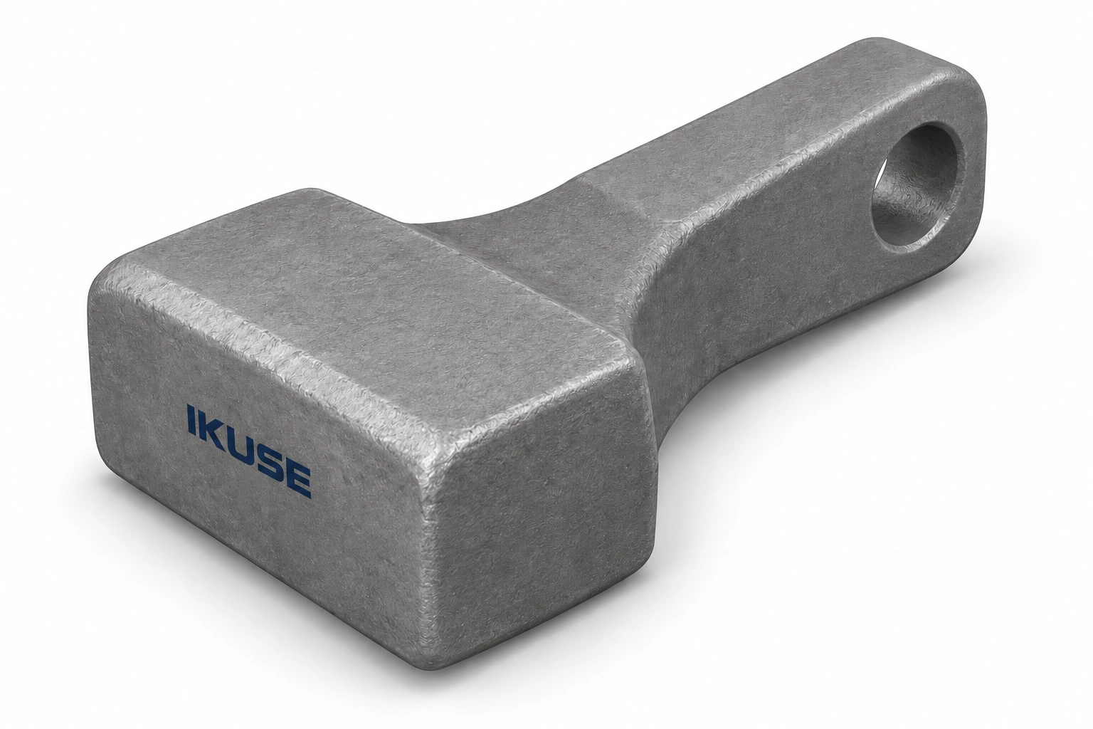
Impact wear parts for the corresponding hammer-crushing equipment. The working head, neck, mounting interface and mass grouping must match the machine and feed conditions.
Design and configuration
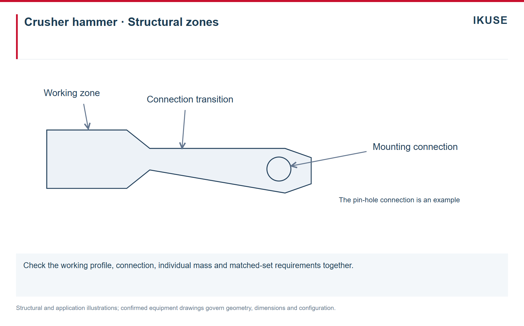
Check the head contour, neck transition, mounting bore, mating dimensions, direction and surrounding movement clearance. Selection based only on the working-end appearance is insufficient.
Crusher hammer · Structural zones
Check the working profile, connection, individual mass and matched-set requirements together. Structural and application illustrations; confirmed equipment drawings govern geometry, dimensions and configuration.
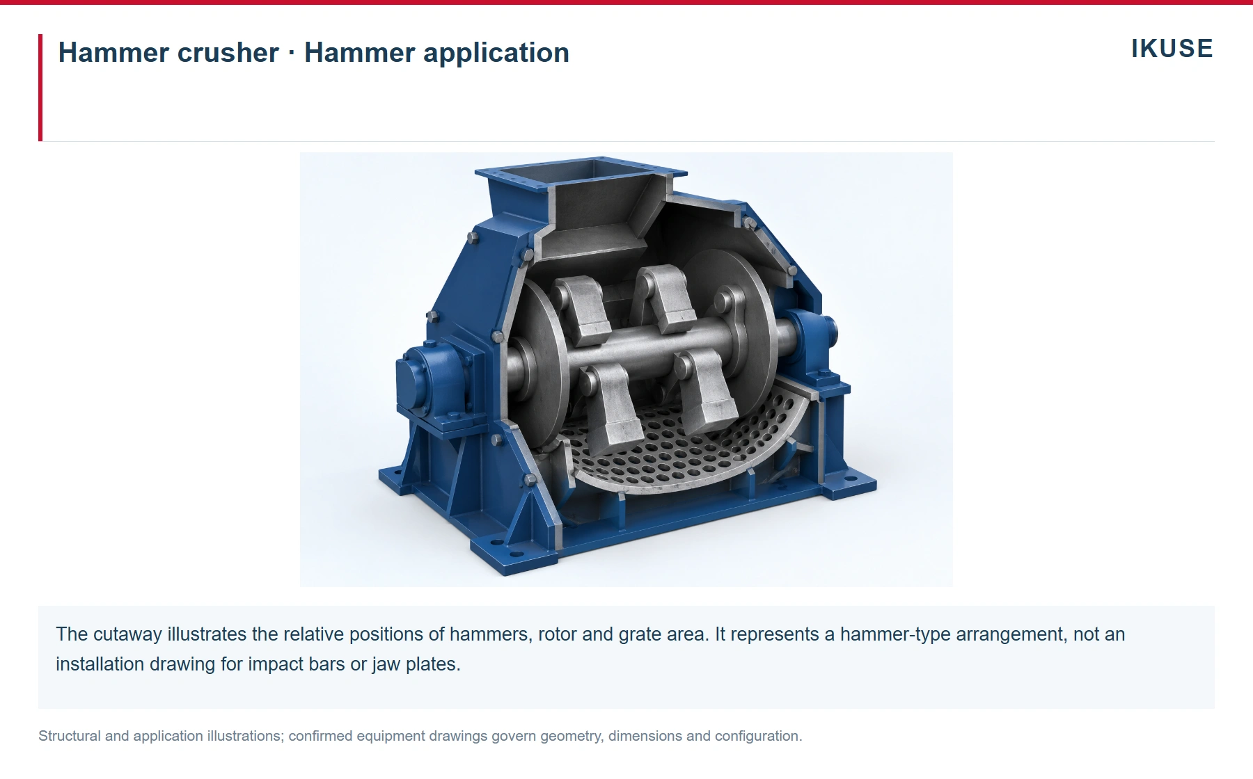
Hammer crusher · Hammer application
The cutaway illustrates the relative positions of hammers, rotor and grate area. It represents a hammer-type arrangement, not an installation drawing for impact bars or jaw plates. Structural and application illustrations; confirmed equipment drawings govern geometry, dimensions and configuration.
Operating conditions and installation
Feed size, abrasiveness, impact severity and foreign material affect selection. Confirm individual mass and grouping requirements from the equipment documents. Hammers and fixed blow bars must be selected for their respective machines.
Inspection and maintenance
Separate working-face wear from sudden fracture and damage at mounting interfaces. Record the installation position, operating period, feed changes and condition of the matching parts; follow the equipment maintenance requirements.
Information for enquiries
Provide crusher model, hammer drawing and part number, connection dimensions, individual mass, grouping requirements and quantity. Include feed information, photographs and the principal wear or fracture locations.
Product illustration
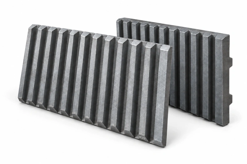
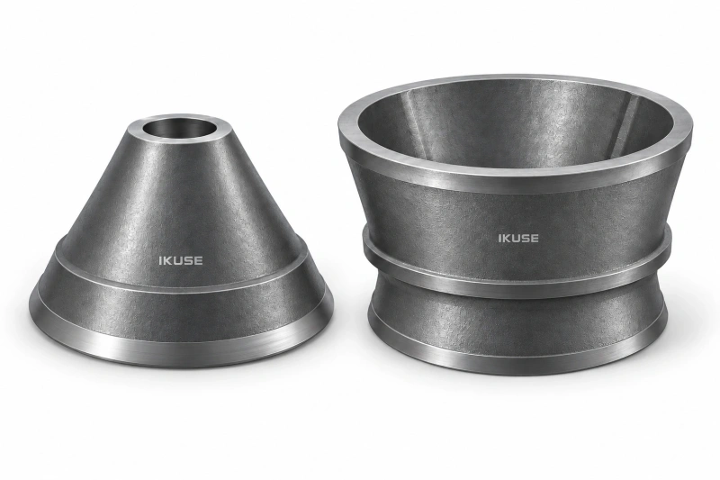
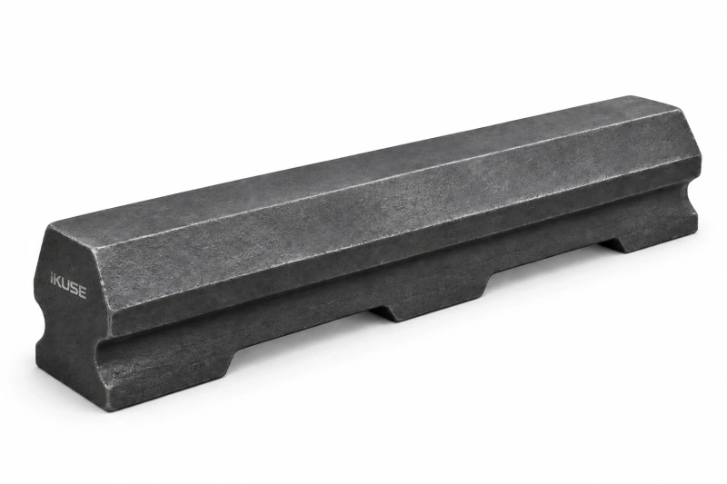
Illustrations show typical structural arrangements. Materials, dimensions, interfaces and supply scope are subject to the approved drawings and technical documents.